The stators are bearing-mounted types, which can be easily set in place on the shafts.Two types are available for different shaft RPMs: a dry metal type and a ball bearing type. Miki Pulley has experience making a wide array of products customized to customer requirements by assembling three types of armatures with pulleys and gears and then combining these with shafts.
Specifications
Downloads
CYT Models (Custom micro clutches)
CYT Models
[Specifications]
| Model | Size | Dynamic friction torque Td [N・m] | Coil (at 20℃) | Heat resistance class | Lead wire | Max. rotation speed [min-1] | Rotating part moment of inertia | Allowable engaging energy Eeaℓ [J] | Total work ET [J] | Armature pull-in time ta [s] | Torque rise time tp [s] | Torque extinction time td [s] | Mass [kg] | |||||
|---|---|---|---|---|---|---|---|---|---|---|---|---|---|---|---|---|---|---|
| Voltage [V] | Wattage [W] | Current [A] | Resistance [Ω] | UL style | Size | Armature [kg・m2] | Rotor [kg・m2] | |||||||||||
| CYT-025-33B | 025 | 0.4 | DC24 | 4.5 | 0.188 | 128 | B | UL3398 | AWG26 | 3600 | 1.00×10⁻⁶ | 1.43×10⁻⁶ | 800 | 1.0×10⁶ | 0.014 | 0.028 | 0.030 | 0.07 |
| CYT-03-33B | 03 | 0.5 | DC24 | 5.5 | 0.23 | 105 | B | UL3398 | AWG26 | 3600 | 1.30×10⁻⁶ | 1.85×10⁻⁶ | 900 | 1.5×10⁶ | 0.015 | 0.030 | 0.040 | 0.13 |
| CYT-03-33M | 03 | 0.5 | DC24 | 5.5 | 0.23 | 105 | B | UL3398 | AWG26 | 500 | 1.30×10⁻⁶ | 1.90×10⁻⁶ | 900 | 1.5×10⁶ | 0.015 | 0.030 | 0.040 | 0.11 |
| CYT-04-33B | 04 | 1.0 | DC24 | 5.9 | 0.25 | 98 | B | UL3398 | AWG26 | 3600 | 5.15×10⁻⁶ | 1.00×10⁻⁵ | 1900 | 2.0×10⁶ | 0.030 | 0.040 | 0.040 | 0.26 |
| CYT-04-33M | 04 | 1.0 | DC24 | 5.9 | 0.25 | 98 | B | UL3398 | AWG26 | 500 | 5.15×10⁻⁶ | 1.05×10⁻⁵ | 1900 | 2.0×10⁶ | 0.030 | 0.040 | 0.040 | 0.23 |
*The dynamic friction torque, Td, is measured at a relative speed of 100 min-1. Depending on the initial torque characteristics, break-in to condition the engaging surfaces may also be required.
*Keep supply voltage fluctuation to within 10% of coil voltage. Also, be careful that energization does not exceed 50%.
*The rotating part moment of inertia and mass are measured for the maximum bore diameter.
[Dimensions]
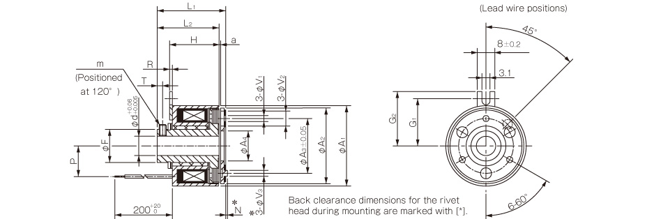
CYT-□-33M

| Size | Radial direction dimensions | Axial direction dimensions | ||||||||||||||||||
|---|---|---|---|---|---|---|---|---|---|---|---|---|---|---|---|---|---|---|---|---|
| d | A1 | A2 | A3 | A4 | F | V1 | V2 | V3 | G1 | G2 | m | H | R | L1 | L2 | P | N | T | a | |
| 03 | 6 | 34 | 32 | 23 | 12.5 | 14 | 3 to 2.6 | 3 to 5.5 | 3 to 6 | 20 | 23 | M3 | 21 | 1.2 | 28.6 | 26.2 | 13 | 3 | 2.3 | 0.2±0.05 |
| 8 | ||||||||||||||||||||
| 04 | 8 | 45 | 42 | 30 | 18.5 | 18 | 3 to 3.1 | 3 to 6 | 3 to 6 | 25 | 27.5 | M4 | 25.3 | 1.2 | 35.1 | 32.4 | 17.5 | 3.5 | 3 | 0.2+0.05-0.1 |
| 10 | ||||||||||||||||||||
* Dimensional symbols N and V3 indicate the clearance dimensions for the rivet head during mounting.

[Dimensions]
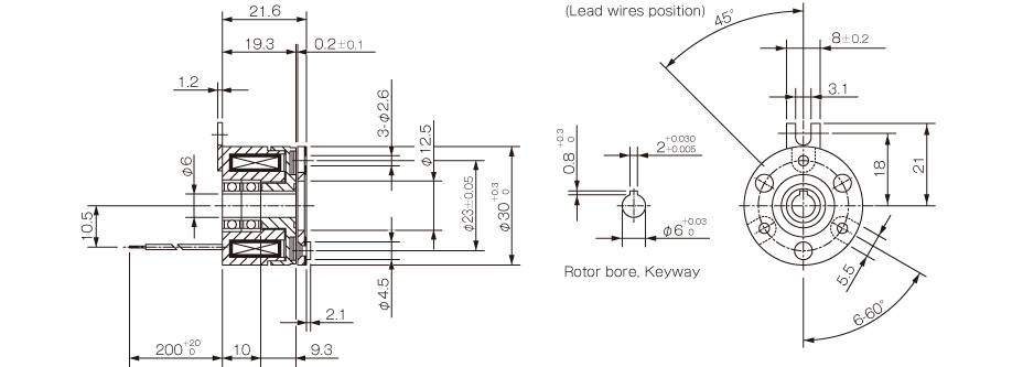
CYT-025-33B


[Dimensions]
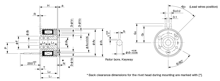
CYT-□-33B

| Size | Nominal diameter | Radial direction dimensions | Axial direction dimensions | Shaft bore dimensions | |||||||||||||||||||||
|---|---|---|---|---|---|---|---|---|---|---|---|---|---|---|---|---|---|---|---|---|---|---|---|---|---|
| A1 | A2 | A3 | A4 | F | V1 | V2 | V3 | G1 | G2 | H | R | L1 | L2 | L3 | L4 | P | N | T | a | d2 | d1 | b | t | ||
| 03 | 6 | 34 | 32 | 23 | 12.5 | 15 | 3 to 2.6 | 3 to 5.5 | 3 to 6 | 20 | 23 | 21 | 1.2 | 22.2 | 19.8 | 10 | 11.3 | 13 | 3 | 1.5 | 0.2±0.05 | 6 | 6 | 2+0.030-0.005 | 0.8+0.30 |
| 8 | 34 | 32 | 23 | 12.5 | 16 | 3 to 2.6 | 3 to 5.5 | 3 to 6 | 20 | 23 | 21 | 1.2 | 22.2 | 19.8 | 10 | 11.3 | 13 | 3 | 1.5 | 0.2±0.05 | 8 | 8 | 2+0.030-0.005 | 0.8+0.30 | |
| 04 | 8 | 45 | 42 | 30 | 18.5 | 19 | 3 to 3.1 | 3 to 6 | 3 to 6 | 25 | 28 | 25.3 | 1.2 | 26.8 | 24.1 | 12 | 13 | 17.5 | 3.5 | 0.9 | 0.2+0.05-0.1 | 8 | 8 | 2+0.030-0.005 | 0.8+0.30 |
| 10 | 45 | 42 | 30 | 18.5 | 19 | 3 to 3.1 | 3 to 6 | 3 to 6 | 25 | 28 | 25.3 | 1.2 | 26.8 | 24.1 | 14 | 11 | 17.5 | 3.5 | 0.9 | 0.2+0.05-0.1 | 10 | 10 | 3+0.025-0 | 1.2+0.30 | |
*Dimensional symbols N and V3 indicate the clearance dimensions for the rivet head during mounting.
